
Automating Custom IoT Devices With Appium, Part 2
This article is the second in a two-part series on using Appium with platforms very different from mobile operating systems. Make sure to read the first part first!
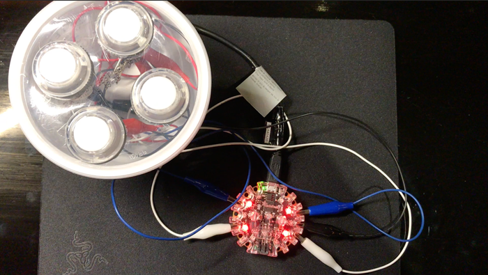
We ended the first part of this series with a fully functional drum machine, powered by a Circuit Playground Express and some simple hardware components like buttons and LEDs. Now we come to the question of how to test this device. As we begin to think about the question, we realize that there are several different places we can insert a test component in the application "stack". For reference, here's the app "stack":
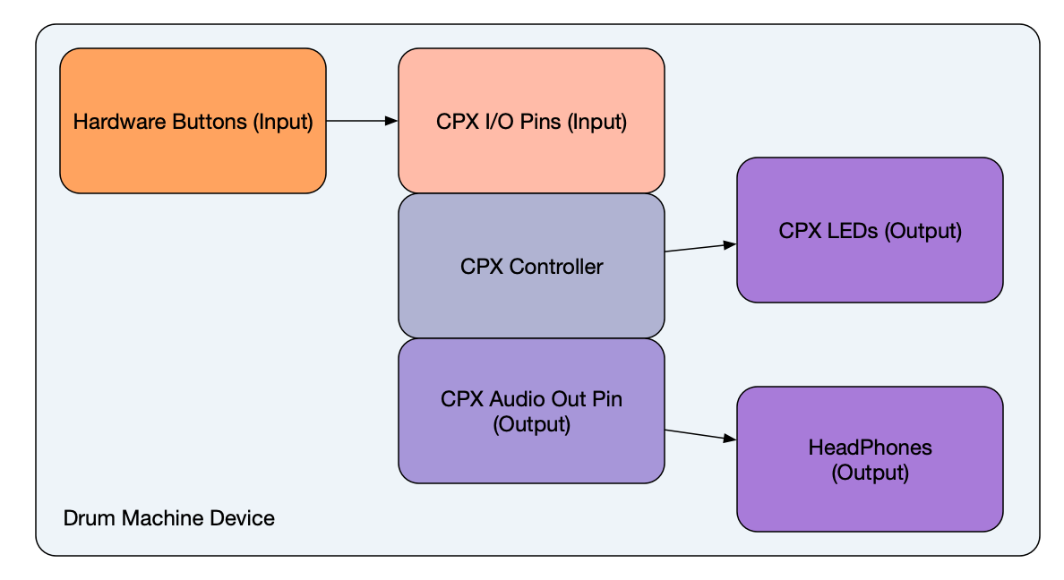
Now, any good test must (1) trigger, synthesize, or simulate some inputs, and (2) validate the outputs. For the purposes of this exploration, we're going to focus on the first half of this--the input automation. (Verifying the output in this case would involve capturing the audio and running it through some kind of audio fingerprint analysis, and setting up a camera or light sensor to track the LEDs.) So just considering the input, we have 3 possible places to hook into the stack with our automation:
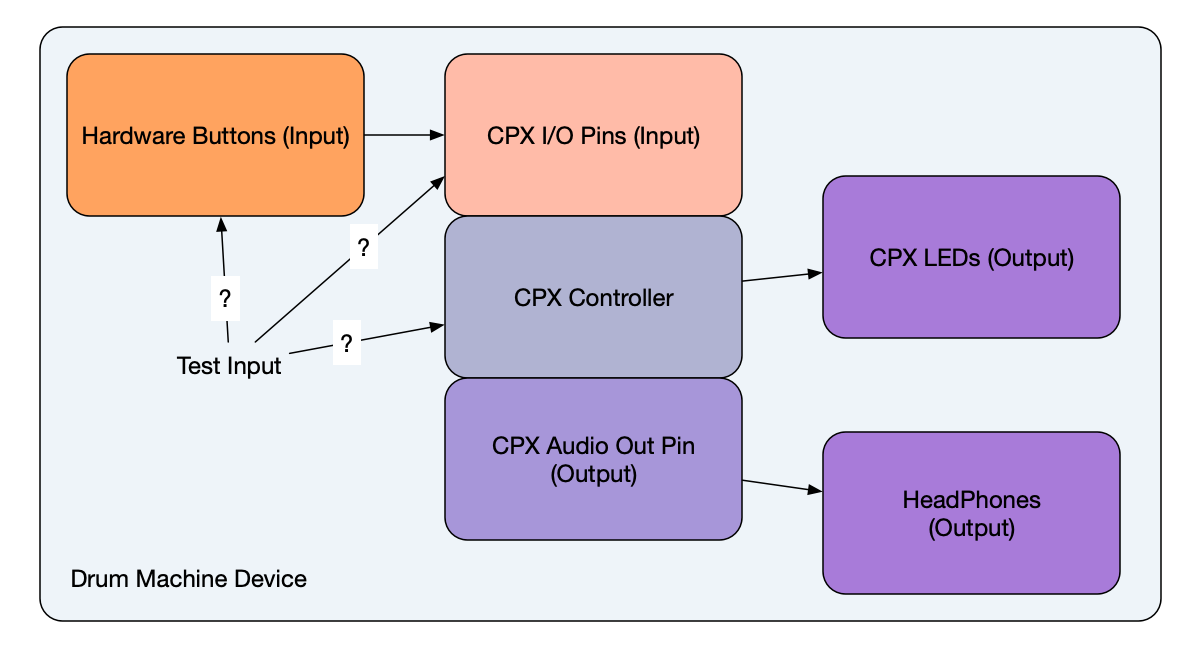
- We could build a robot to press the buttons
- We could create a device to send electrical signals to the I/O pins that the buttons are connected to
- We could write code that triggers the same routines in the processor that are triggered by a button press
So which level of automation should we choose? It really depends on what we care most about testing, and what we have the ability to do. By far the easiest thing to do would be to write code that simply pretends a button has been pressed. But this is pretty unsatisfying, because by doing this we're not actually testing the device, only the microcontroller on to the outputs.
Ultimately, I choose level #2, mostly because I don't know how to build robots that tap buttons on command. And I felt #2 is still a reasonable "end-to-end" test of the drum machine. We're not testing the buttons, true, but we can probably assume they've been well-tested by the button manufacturer. So what we want is a way to trigger electrical signals to the CPX's I/O pins in exactly the same way that a button press would.
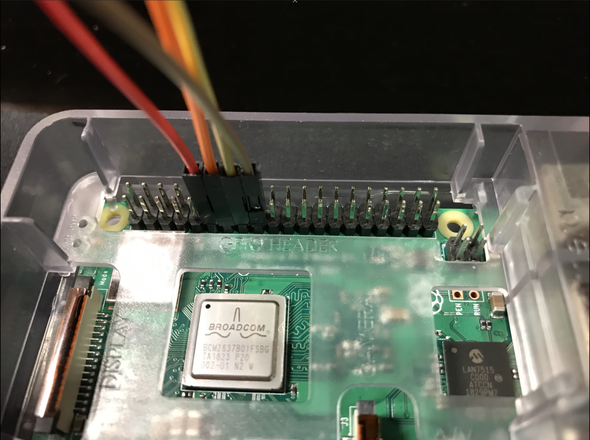
Well, the best way to trigger electrical signals on command is via... another microcontroller! Enter the Raspberry Pi 3 Model B. This is a little computer that happens to have a set of its own GPIO pins. What this means is that we can program a Raspberry Pi to send whatever electrical signals we want, including ones that emulate what happens when the buttons of our drum machine are pressed. This is what our Raspberry Pi looks like with wires attached to the GPIO pins:
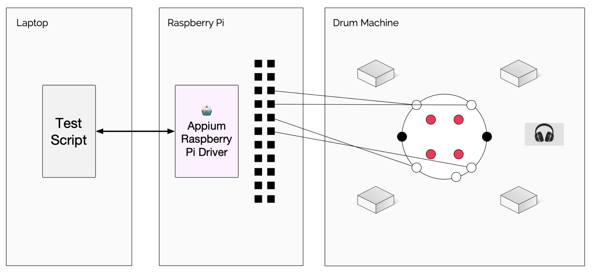
Now all we need is a way to automate the Raspberry Pi GPIO pins, and that is where we can involve Appium, because there is now an Appium driver for the Raspberry Pi. I created this driver with this application in mind, and so it is very limited in its functionality. All it can do is start and stop sessions, and control whether a particular pin is turned on or off. Luckily, that's all we need. Diagrammatically, it looks something like this:
(If you're interested in seeing how the Appium Raspberry Pi driver works under the hood, have a look at its source code. It extends Appium's BaseDriver class, and mixes in functionality from the Johnny Five Node.js library, which enables easy control of the board).
Because the Raspberry Pi is a full-on computer that can run Node.js, we can simply run the Appium driver on it directly (after cloning the repo and running npm install in it, of course, and ensuring our Pi has all the requisite dependencies):
git clone https://github.com/jlipps/appium-raspi-driver.git
cd appium-raspi-driver
npm install

# now start the driver in standalone mode
node . -a raspberrypi.local
Notice that we have to be explicit about the address we want our server to run on, if we want the server to be accessible from a computer running the test script elsewhere on the network (or we could just run the test script on the Pi).
So that takes care of the server, but we still have to worry about writing a test to execute on it. As with any Appium test, there are two basic components to a test using this driver: the capabilities, and the test steps themselves. For the Appium Raspberry Pi driver running in standalone mode, all we need is one capability: app. This capability is very important, because it tells the driver which pins we want to automate, and what their initial states will be. If you think about it, we need to have 3 pieces of information in order to automate this scenario successfully:
- Which pin(s) on the Raspberry Pi are we using to control our device-under-test?
- Which pin(s) on the device-under-test are we targeting for automation?
- What should the initial state of the Raspberry Pi pins be? (I.e., should they be in input or output mode, and set to high or low?)
The reason we care about #2 is that, as we develop our test, we would prefer to work with "elements" whose names correspond to the appropriate places on the device-under-test, not the Raspberry Pi pins themselves (because what if we choose to plug them into different pins next time we run the test? That would make our locators 'brittle'). Ultimately, the app capability I defined looked like this:
{
  pins: {
    'P1-7': { id: 'A1', mode: 'output', init: 1, },
    'P1-11': { id: 'A2', mode: 'output', init: 1, },
    'P1-13': { id: 'A5', mode: 'output', init: 1, },
    'P1-15': { id: 'A6', mode: 'output', init: 1, },
  }
}
In other words, it specifies a set of 4 pin mappings. The name of each pin is its name on the Rasbperry Pi GPIO header. The associated id is the name of the terminal on the CPX that we want to send (or stop sending) electrical signals to. The mode of the pin is either input or output, and init can be either 1 or 0 based on whether we want the initial state of the pin at the beginning of the test to be high or low.
What this app definition allows us to do is work with "elements" in our test code, just as if we were looking for UI elements on a screen:
const kick = await driver.elementById("A1");In this example, we are finding an "element" named "A1". Since we have provided the Raspberry Pi driver with our app config, the driver knows that when we interact with this element, we will be sending signals via the "P1-7" output pin. And of course, we could have named "A1" anything we want, even something more human-readable like "KickDrum"--I chose to name it after the names of the IO pins on the CPX, so I would always know what wires to connect where. (As testers, if we had access to the app code, we could of course auto-generate this app definition to ensure everything works no matter where we've chosen to connect our wires).
OK, so we can find an element. But what can we do with it? The only thing we can do with elements retrieved via this driver is set them to a digital high or low signal, represented by the strings "1" and "0" respectively. To register these values, we use the plain old sendKeys command!
await kick.sendKeys("0")The above command tells the pin represented by the previously-retrieved element to change to a low/zero signal.
That is all that is possible with the current state of the Appium Raspberry Pi driver, though in the future it would be easy to add support for higher-level components available on the Pi via the Johnny Five API---but for the sake of simply driving another electronic device via signals in this way, the current set of commands is all we need.
So all that remains for us is to actually write some test code! Here's the code I used in my AppiumConf 2019 talk demo. It's written in JavaScript, because that was the language that I felt most comfortable developing the non-Appium portions of the code is (the code responsible for parsing a musical notation string into WebDriver commands). But like any Appium script, this could have been written in any language. First of all, let's look at the main function:
(async function main () {
  driver = wd('http://raspberrypi.local:7774/wd/hub');
  await driver.init({app});
  await B.delay(2000);
  try {
    const kick = await driver.elementById("A1");
    const snare = await driver.elementById("A2");
    const hat = await driver.elementById("A5");
    const tom = await driver.elementById("A6");
    const elMap = {k: kick, s: snare, h: hat, t: tom};
    const song = `
      k4 k4 s8 k4 k8
      k4 k4 s8 k8 s8 s8
      h4 k4 s8 k4 k8
      k4 k4 s8 k8 t8 t8
      h4
    `;
    await playSong(song, elMap);
  } finally {
    await driver.quit();
  }
})().catch(console.error);
You can immediately see that this isn't a proper test, just an automation script (there's no test method or assertions, just plain old JS functions). We first connect to the Appium Raspberry Pi driver running on the Pi at its default port of 4774 (this is where it was important to start the driver with a non-default address, so that connecting to it over Ethernet works). Then, we pass in our app definition (as shown above). Finally, we assign names to our different pin elements, and then call a custom playSong method which directs the client to send the right signals at the right time based on what is defined in song.
The implementation of playSong isn't important to show here, but what is important is that somewhere inside that method are a bunch of calls to another method hit, which does the actual work:
async function hit (el, delay=HIT_HOLD_MS) {
  await el.sendKeys("0");
  await B.delay(delay);
  await el.sendKeys("1");
}
You can see here that there's really no magic involved: we simply turn a pin's signal off and on in order to emulate the act of pressing a button on a device. (If you're confused, like I was, why we have to turn the signal off in order to trigger a drum hit, it appears to be because that's how the button is designed--when it is pressed down, it breaks the circuit, so that is how I programmed the CPX to recognize a drum hit. Therefore we have to follow the same pattern with our test logic, and that is why the initial state of all the pins was set to 1).
There you go! As I said above, this is really only half of a true test, since there is no verification involved, but it does show how, with a little bit of imagination and creativity, the Appium framework can be repurposed for applications very different from traditional screen-based UI apps. The Appium Raspberry Pi driver is available for you to use however you wish. In fact, the Raspberry Pi is probably overkill for the purpose of simply driving electrical signals to a device under test. Something like one of the smaller Arduinos would probably be more appropriate---I just happened to have a Pi on hand!
If you want to see my full test script in the context of a whole project, you can find it on GitHub. Please let me know if you find any interesting uses for this approach, or end up doing something similar for your own IoT devices!